What are the differences between NdFeB magnets of different shapes?
1. 6 standard shapes of NdFeB magnets
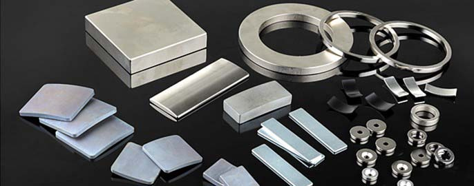
The shape of NdFeB magnets is mainly selected based on factors such as installation space, force direction, magnetic circuit design, etc. The following are 6 common NdFeB magnets with different shapes:
| Shape | Dimensions Range | Tolerance | Top Uses | Performance Tip |
| Discs | Ø1-100mm, T0.5-20mm | ±0.05mm | Sensors, Audio Devices | Higher thickness → stronger axial pull force |
| Blocks | L0.5-150mm, W1-100mm | ±0.1mm | MRI, Magnetic Chucks | Add chamfers to prevent chipping |
| Cylinders | Ø1-50mm, H1-100mm | ±0.1mm | Stepper Motors | Height/Diameter ratio affects radial field |
| Rings | ID/OD: 2-120mm | ±0.05mm | Encoders, Generators | Thin walls (<1mm) require epoxy coating |
| Arcs Angle | 30-180°,R±0.1mm | ±0.05° | Wind Turbine Generators | Segment count reduces cogging torque |
| Countersunk | 90°/120° | ±0.1mm | Automotive Assemblies | Zinc plating prevents screw corrosion |
2. What are the differences in the production of NdFeB magnets of different shapes?
Dics: A simple mold (cylindrical) is sufficient for dry pressing. During processing, uniform diameter and thickness must be maintained, using centerless grinding and surface grinding.
Blocks: The mold has a square cavity. During processing, vertical corners must be maintained. The upper and lower surfaces are surface-grinded, and trimming is performed with a grinding wheel.
Rings: A “hollow mold” is used for isostatic pressing (to avoid center porosity). The inner and outer diameters and end faces must be machined, using internal and external grinding. If steps or grooves are present, wire cutting is used.
Irregular: Custom complex molds (such as arcs, trapezoids, and polygons) are used, or the shape is initially pressed to an approximate shape. Wire cutting (slow wire cutting, ±0.01mm accuracy) or 3D laser cutting (for complex curved surfaces) is primarily used, resulting in lower processing efficiency.
3. How does magnet geometry affect performance?
The shape of NdFeB magnets is not simply a “selection of appearance”, but a core factor that directly determines the efficiency of its magnetic performance, reliability of use and feasibility of industrial application. The main considerations are the optimization of magnetic flux distribution and the guarantee of mechanical stability, and an in-depth analysis is conducted in combination with actual application scenarios.
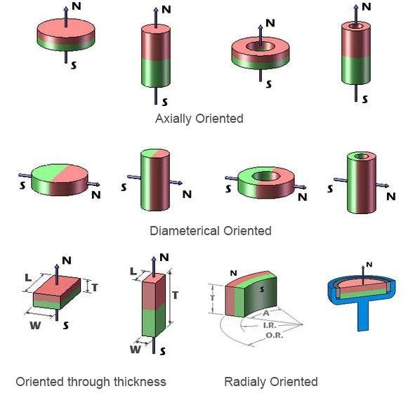
(1) Magnetic flux distribution
The distribution law of magnetic flux is “closed along the path with minimum magnetic resistance”. Different shapes can guide the direction of the magnetic field by adjusting the “pole area and magnetic path length”.
- Ring magnets: The size ratio of the inner and outer diameters determines the radial/axial magnetic field distribution.
- Block Magnets: Their large planar magnetic pole area makes them suitable for surface-contact magnetic field applications (such as speaker magnets).
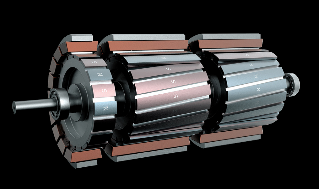
- Special-Shaped Magnets (such as arc-shaped and trapezoidal): Customized for non-planar magnetic circuits. For example, the “magnetic tiles” (arc-shaped NdFeB magnets) used in new energy vehicle drive motors must perfectly align with the arc-shaped slots in the motor’s rotor core to ensure uniform magnetic flux distribution along the rotor’s circumference (forming a sinusoidal magnetic field). Substituting these with ordinary circular magnets results in concentrated and sparse magnetic flux in some areas, increasing torque fluctuations (cogging torque) during motor operation, leading to increased noise and energy consumption.
For NdFeB magnets of the same volume and brand, the actual usable magnetic flux can vary by 20%-40% depending on their shape. Therefore, it is important to minimize magnetic flux waste and maximize magnetic performance utilization.
(2) Mechanical stability
Neodymium magnets (especially sintered types) are physically “hard but brittle” . Their shape design directly impacts their ability to withstand external forces and their uniformity in force distribution, determining their service life under conditions such as vibration, shock, and high temperatures.
- For axial load scenarios (such as magnetic chucks): Use a disc-shaped or cylindrical shape to ensure uniform axial force across the entire magnetic pole surface, avoiding localized excessive force that could cause magnet misalignment.
- For radial load scenarios (such as motor rotor magnets): Use arc magnets. Their curvature perfectly matches the rotor core. After assembly, they are secured with epoxy resin, ensuring that centrifugal forces during radial rotation are evenly distributed across the core.
- Thickness and structure matching: Special-shaped NdFeB magnets used in robotic joints must avoid being locally too thin (e.g., cantilever structures with a thickness of less than 3mm). These thin, brittle structures generate bending stresses due to centrifugal force and torque during joint rotation, potentially causing cracks in the short term.
Different application scenarios require different load types (e.g., axial tension, radial compression, and torque). Therefore, the shape must be matched to the load direction to adapt to the operating conditions and improve structural reliability.
4. What are the differences in performance between NdFeB magnets of different shapes?
When the object to be attracted is a “small magnetically permeable body” (such as an iron nail or a small iron sheet, whose size is much smaller than that of the magnet), the attractive force is mainly determined by the “magnetic dipole force” exerted by the magnetic field on the surface of the magnet on the small magnetically permeable body. The formula is derived as follows:
F = (B1² × A) / (2μ₀)
F: Magnetic attractive force(N);
B₁: Magnetic flux density at the contact point between the magnet and the small magnetically permeable body(T) ;
A: Effective contact area between the magnet and the small magnetically permeable body(m²) ;
μ₀: Permeability of free space ( μ₀ = 4π×10⁻⁷ H/m)
- Volume/Weight: For the same brand, the larger the volume, the greater the total magnetic flux and the greater the suction force.
- Magnetic Pole Area: The suction force is positively correlated with the “magnetic pole surface area” (for the same volume).
- Shape Symmetry: Symmetrical shapes (circle/square) have a more uniform magnetic field distribution and better suction stability than irregular shapes (irregular shapes may experience uneven suction due to localized magnetic field concentration).
- Shape and Orientation: The length of the magnet’s orientation often plays a decisive role in the suction force. A tall, thin magnet may have a much greater attractive force in the orientation direction than a flat, wide magnet of the same weight.